1
Ask Electronics
3173 readers
3 users here now
For questions about component-level electronic circuits, tools and equipment.
Rules
1: Be nice.
2: Be on-topic (eg: Electronic, not electrical).
3: No commercial stuff, buying, selling or valuations.
4: Be safe.
founded 1 year ago
MODERATORS
2
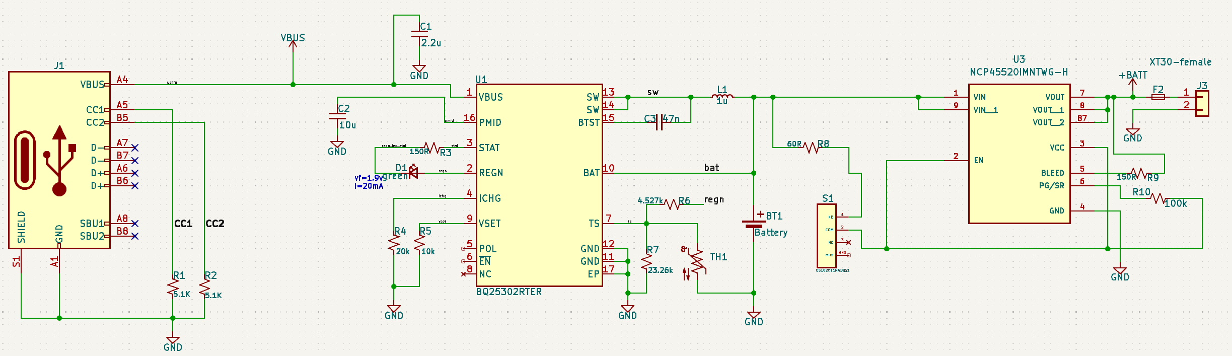
I've been messing around with circuits my entire life but this design was time sensitive and I've never done my own PCB designs before, so I hired someone to put this together. After getting some test boards, when I plug them in the charger chip gets very hot and smells like burning....
Circuit is just a simple li-ion usb charger and a switch. I've gone through the datasheet for the bq25302 more times than I can count and I'm missing something obvious here. Using it just for delivering power seems to work fine, the problem is only when charging.
I do see R6 + R7 off TS don't have the recommended 10k values, but I don't feel like that would cause what I'm seeing. This is being connected to a 21700 lipo.
Someone mind lending me their eyes please?
bq25302 datasheet - https://www.ti.com/lit/ds/symlink/bq25302.pdf
3
4
I asked a while ago, how to build an automatic light switch and finally got around to actually building it.
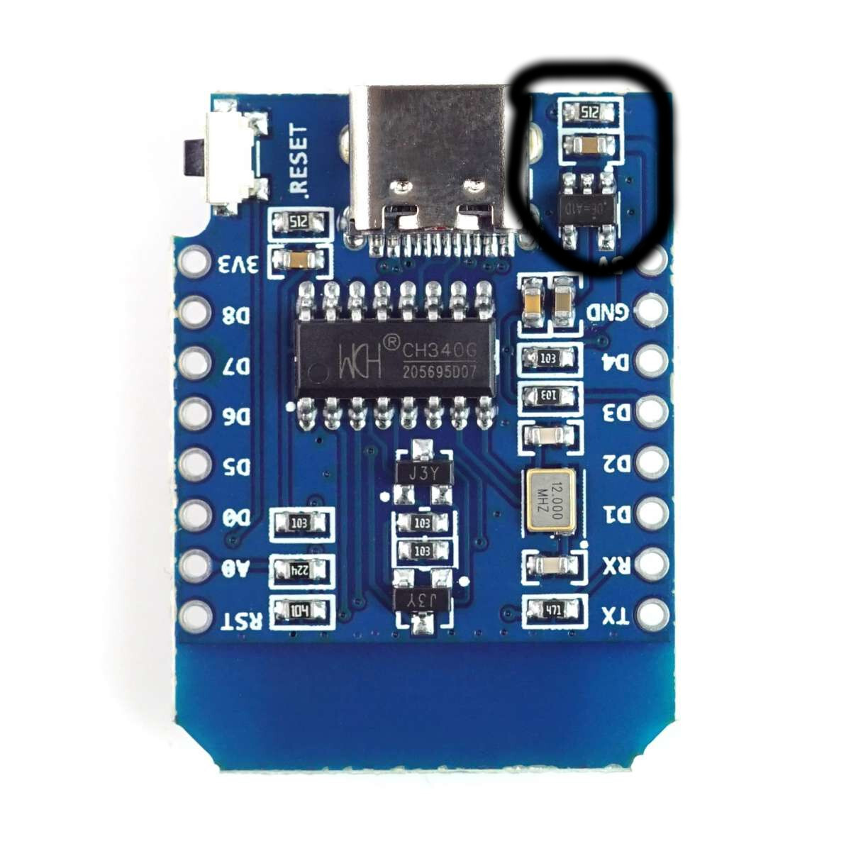
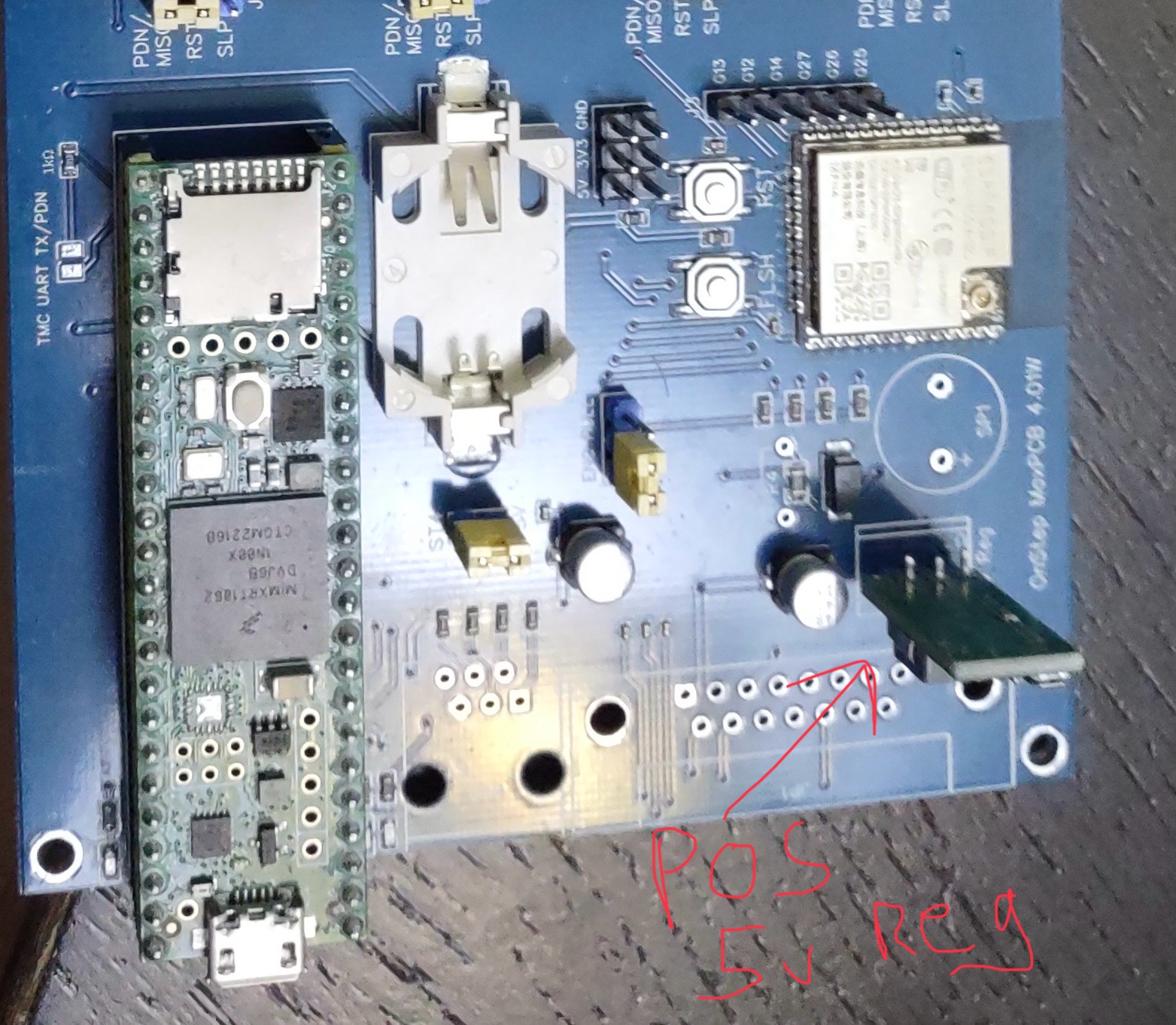
My board is an ESP8266 mini D, and ignoring all the sensor parts, my problem right now is powering the actual light.
It's just a small LED array and I connected it directly to the 5V and GND pins (controlled via a transistor).
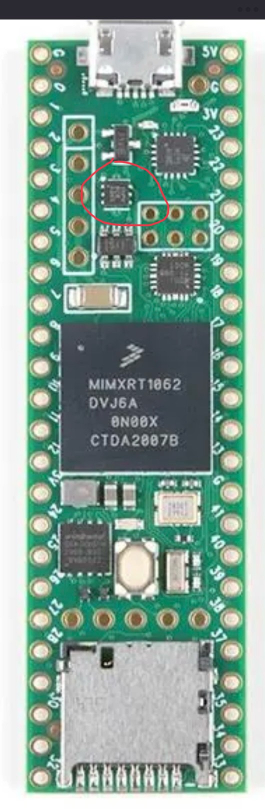
Measuring from the wall (so including the PSU), this whole setup pulls about 3W (so far expected), however, one small component close to the USB connector gets uncomfortably warm, and I'm not sure, whether that's ok.
The hot component is one of the two small thingies circled in the picture. I thought the 5V get pulled directly from the USB plug, so I'm not sure, why there is any circuitry involved.
5
6
19
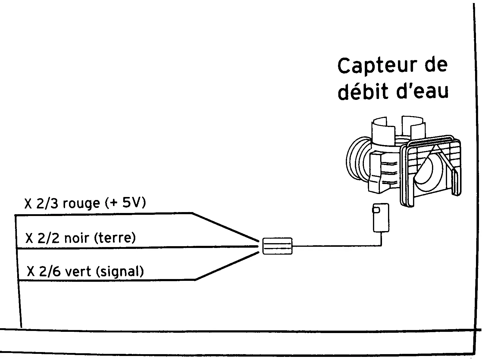
[solved] help needed to understand this diagram of a water flow sensor (from a boiler)
(lemmy.dbzer0.com)
cross-posted from: https://lemmy.dbzer0.com/post/26703241
This diagram is from the service manual of a combi boiler. It’s a flow sensor which detects whether hot water is running, which is then used to trigger on-demand heat and switch a diverter to take radiators out of the loop.
In English, the diagram shows:
- X ⅔ red wire (+5V)
- X 2/2 black wire (ground)
- X 2/6 green wire (signal)
I need to know what those fractions mean. I took the voltage measurements in this video:
I cannot necessarily trust the model in that video to have the same specs as mine. My voltmeter detected 4.68 V on the red input wire showing that the sensor is well fed. The green “signal” wire is supposed to be 0 V at rest and 2 V with water running (or I think the reverse of that is used in some models). In my case the green wire is ~1.33 V at rest and ~0.66 V when water is running. I need to know if these readings are normal as I troubleshoot this problem.
update
@[email protected] and a couple others gave the answer I was after. Then @[email protected] helped solve the underlying problem. The theory that the sensor was fine but the board was not drove me to test the sensor in isolation. The sensor gave correct output in isolation. Then I connected it back to the motherboard to retest and reconfirm that it’s still broken. But it actually worked. The hot water suddenly and mysteriously works now. I guess the act of draining the water and unplugging the connector then reconnecting and repressurizing caused it to work. It may be temporary, since in the past it was hit or miss whether it would work.
7
8
9
Hi there
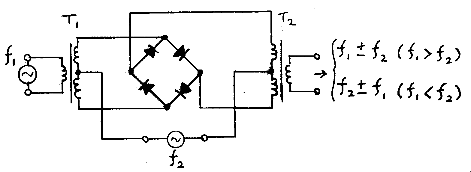
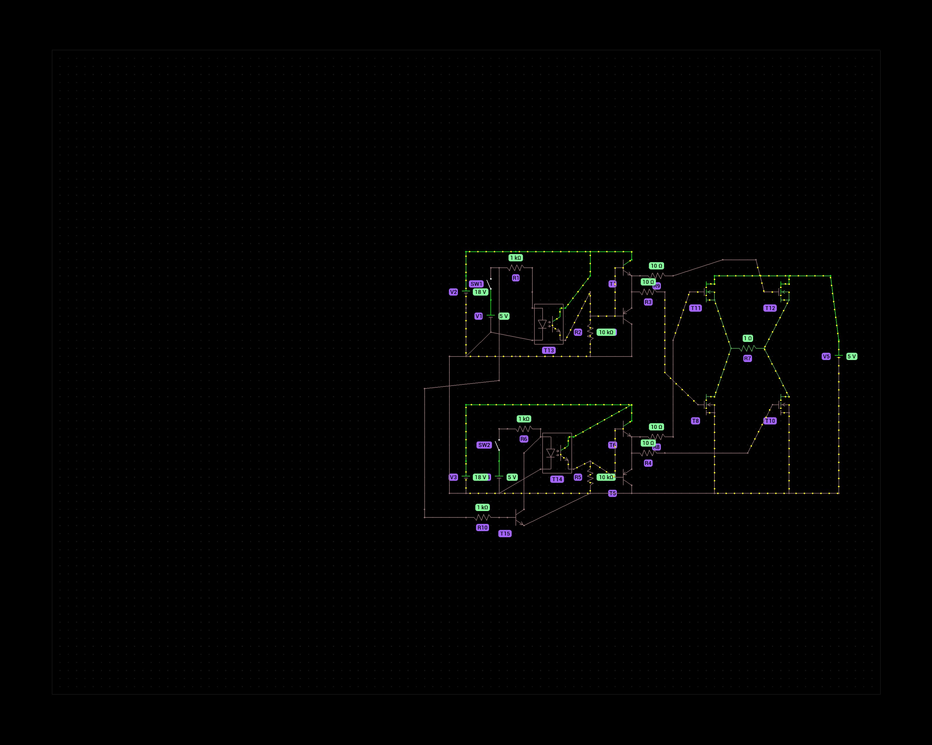
The purpose of this schematic is to control a DC motor that runs at 8V max. That is why I chose 4 N-channel mosfets in the H bridge. P-channels would not fully activate at voltages above -10Vgs but the N-channels can handle 18V at the gate.
The 5v switches represent an Arduino's digital output pins. One to turn forward, one for reverse. To prevent a failure scenario where both pins are HIGH I added a transistor that prevents current from flowing through the optocoupler on the second half bridge.
Does this circuit make sense? I'm not an electronics engineer, just a hobbyist and have doubts about how effective the gate driving circuit is of the mosfets.
Thanks!
10
11
12
13
14
15
16
17
18
19
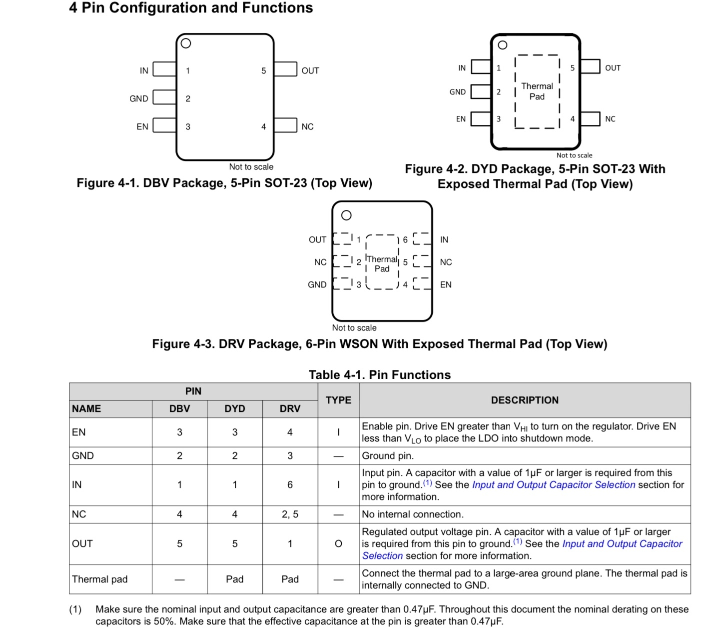
I have a project that is using a Teensy 4.1, the cheep 5v regulator I was using in the project let the magic smoke out for no good reason. I replaced that but now the Teensy boots and runs for about a min then quits. There is a TLV75733P power IC that is supplying the 3v3 and it gets hot then quits supplying power. Since that IC is $0.46 vs a new Teensy 4.1 ~ $40 I want to try and replace it. I have done a bit of SMD work but not tried to remove a tiny chip with a GND pad before so I’m looking for any tips. The PCB of the Teensy has header pins so I can’t really get good contact to a hot plate to preheat the board.

20
21
22
23
24
25
view more: next ›