this post was submitted on 27 Dec 2024
24 points (96.2% liked)
Amateur Radio
1114 readers
22 users here now
General amateur radio (ham radio) chat, questions, and news
founded 2 years ago
MODERATORS
you are viewing a single comment's thread
view the rest of the comments
view the rest of the comments

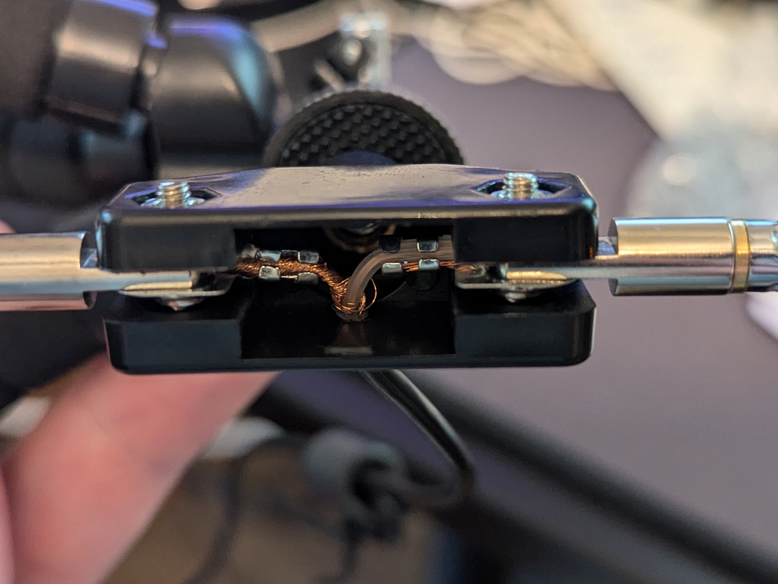
Neither side is ground. Due to electromagnetic field behavior, coax carries equal and opposite AC currents on the inner conductor and the inside surface of the shield; those equal and opposite currents drive the two dipole elements.
RF doesn’t penetrate shielded boxes and coax shields - so the outer surface and inner surface of the coax shield are seen as two different conductors at RF. In the pictured dipole, RF can flow out of the coax and back down the outside (and around the outside of the shielded receiver it’s connected to) because the open end of the coax “connects” them. So the coax shield is very much energized with (and receiving) RF; generally a ferrite bead choke is used to mitigate the unwanted shield currents.
With RF, “ground” doesn’t mean very much. There always has to be a circuit for current to flow; tying some point of the circuit to the chassis or to the power supply negative does not “zero it out” at all.
Let me rephrase (your answer may be the same). I know with some antennas there is a "ground plane" type of element that should be on the bottom. For a vertical dipole is this not the case?
You do seem to be right. It should not matter in theory, but it may be better for the one connected to the center (right on this image) to be up.
Source: https://www.rtl-sdr.com/using-our-new-dipole-antenna-kit/
Weird that they don't elaborate. I flipped it last night and it seemed marginally better this way, so maybe there is some truth to it. Take this with a truck load of salt as it wasn't any sort of controlled experiment at all.
in your antenna, the outside of the coax makes up part of the radiating structure. The orientation of the elements in relationship to that coax will definitely change the radiation pattern, maybe for the better maybe for the worse.
putting ferrites around the coax right below the antenna feed point will make the antenna more symmetrical as it blocks RF currents traveling back down the outside of the shield.
It has a choke on it, it's a little blurry but you can see it. Should it be moved closer? I saw a comment on rtl-sdr's blog suggesting it.
It does not matter. (It does not matter in a “ground plane” antenna either, the radials have nothing to do with the earth other than being easier to mount with the coax heading downward; in fact, radials should not be touching or buried in the earth as they are RF radiators and RF faces high losses in soil)