zumlin

joined 1 year ago
[–] [email protected] 3 points 1 year ago
[–] [email protected] 3 points 1 year ago (2 children)

Wow so shiny. Is that a 3D printed spacer? Did you put it in front of the glass lens?

[–] [email protected] 3 points 1 year ago

Yes and no. While you can use the aux in all the strobes with the latest firmware, there are still only 2 brightness levels (a hardware limitation), and not all of them work like you would expect.

At the moment:

  • You cannot ramp up and down, there is only a high mode
  • Candl mode and biker strobe are just constantly on in high mode and the brightness cannot be changed
  • Party strobe (low mode) and tactical strobe (high mode) work
  • Lightning mode partially works (alternates between off and high mode at random intervals)
[–] [email protected] 1 points 1 year ago

Yes I have installed the new multi-channel branch on all my TS10s. I suppose if you want to use the aux as a channel then you could prefer it to be brighter.

For myself, my aux leds are in high mode when in standby, and go to low mode when auto-lockout kicks in.

[–] [email protected] 4 points 1 year ago* (last edited 1 year ago) (1 children)

I use two pairs of vice grip pliers, one on the head and one on the bezel, with some leather to protect the finish. Heating the bezel up by dipping it in some freshly boiled water should make it easier.

Using this method I have removed many bezels (TS10/SP10 Pro/FW1A Pro) uneventfully. Removing the tail is another story though, because the leather just keeps slipping on the smooth parts of the tube/tail.


I received this copper TS10 a few days ago and I finally got some time to do that mod that I also do when I receive a TS10.

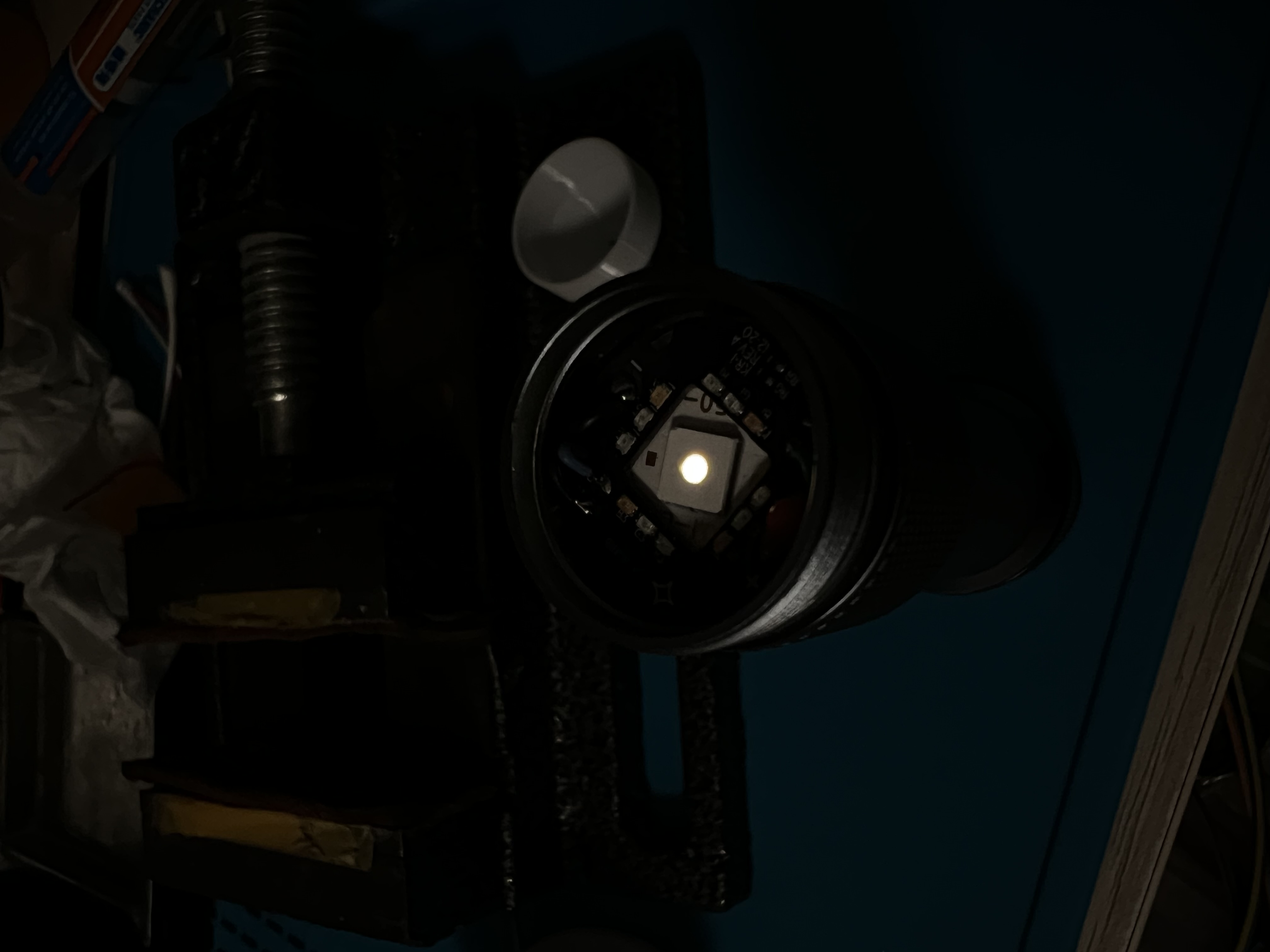
When shipped, the aux leds (regardless of colour) are always too bright and drain the battery too fast for my liking.

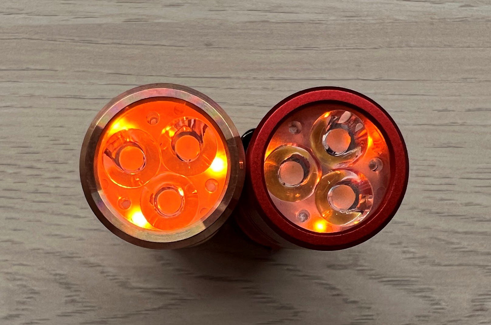
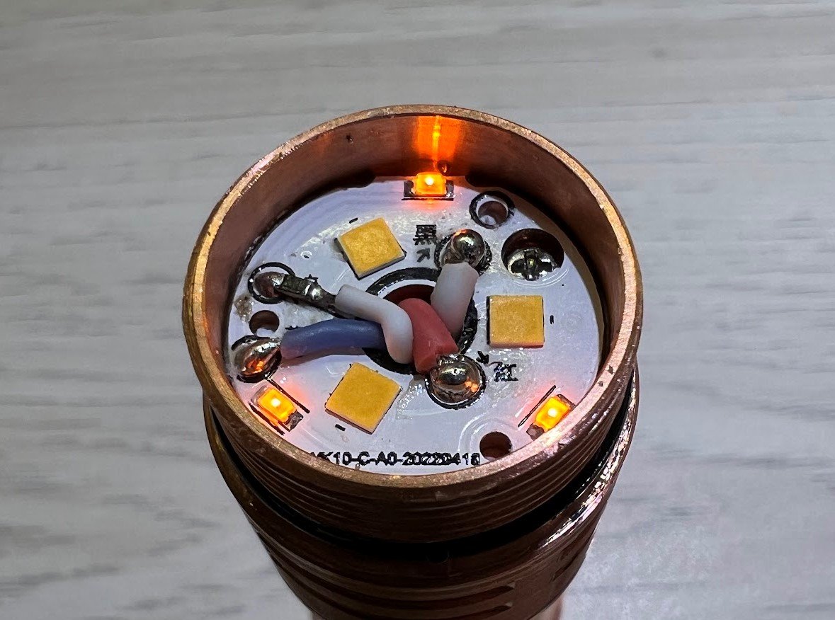
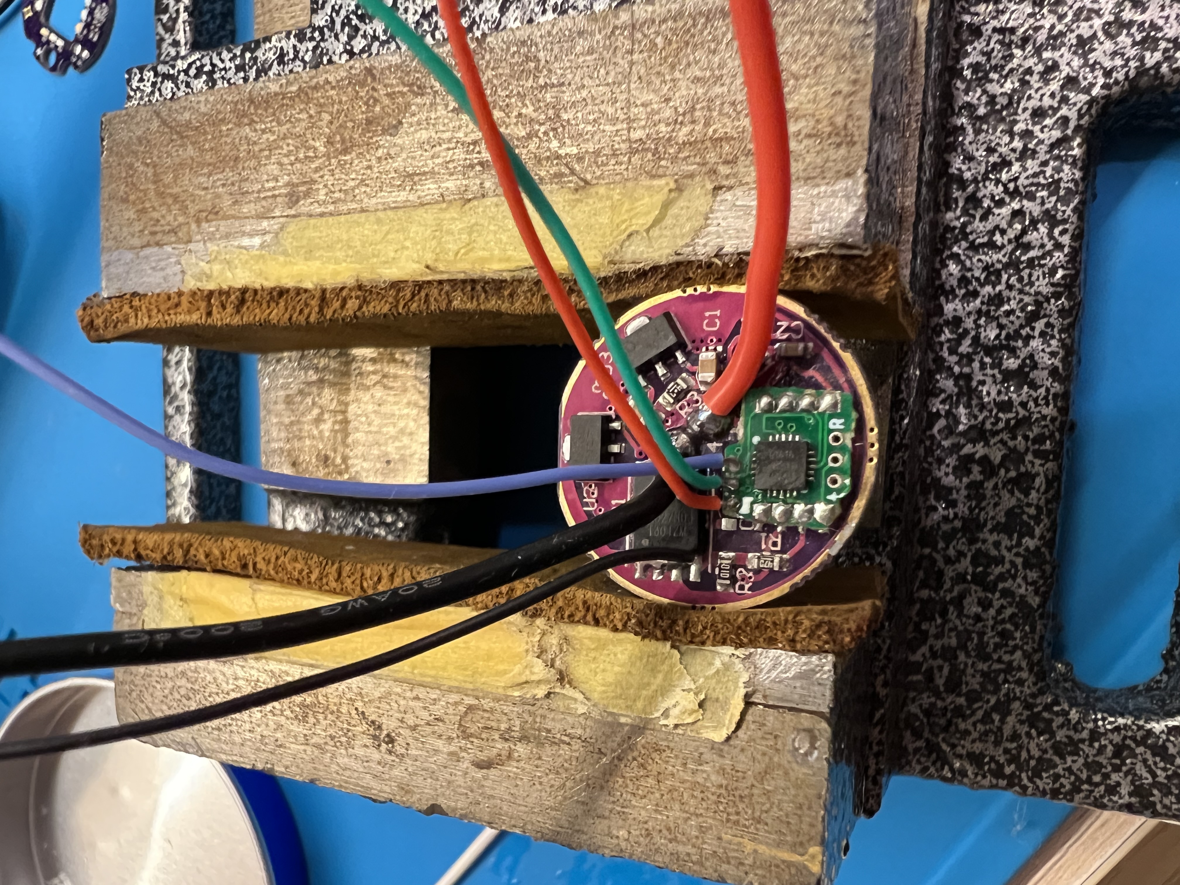
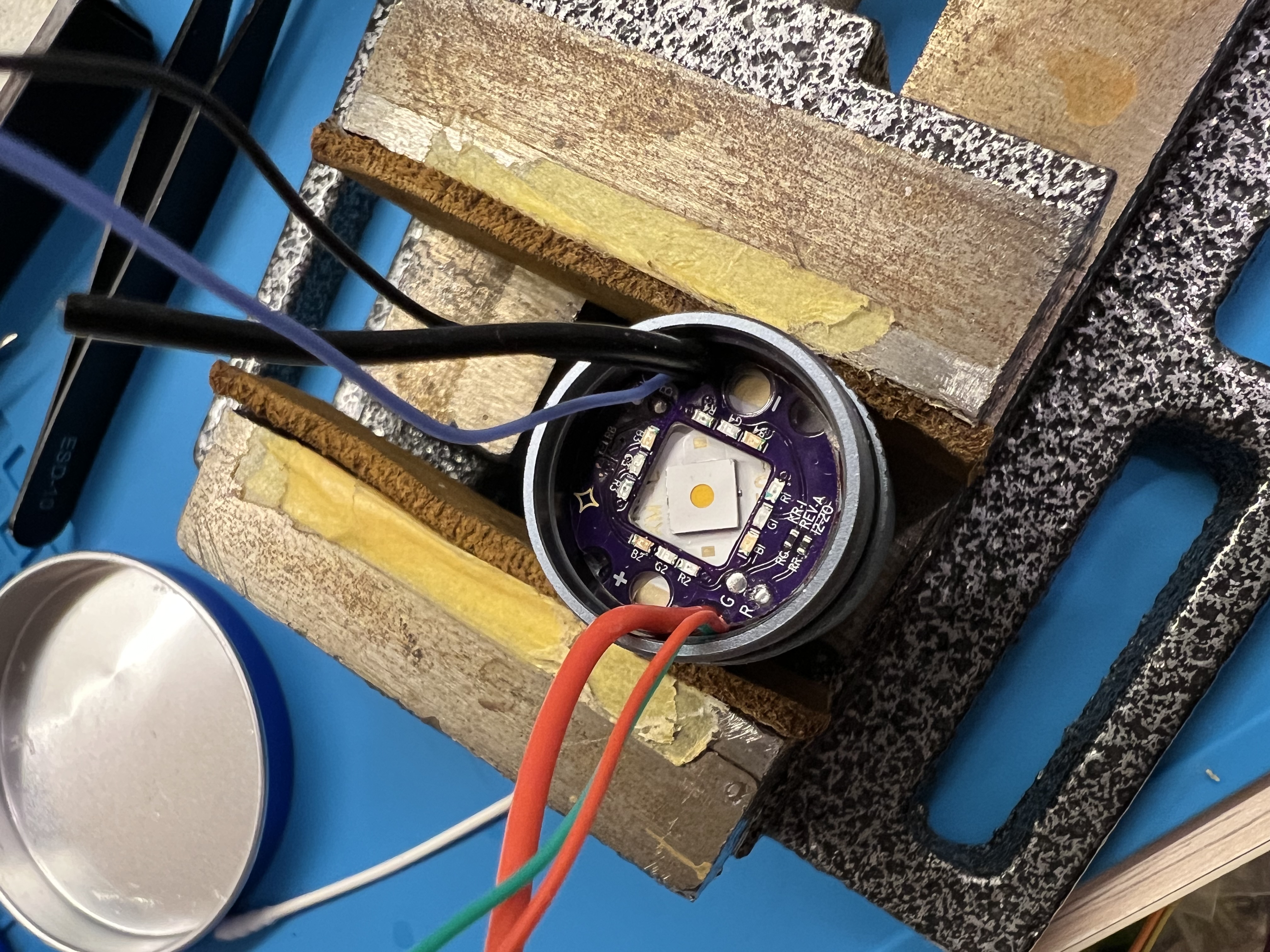
For the orange aux, I added a 510Ω resistor, which dims it down to a comfortable brightness IMO. I don't have the numbers right now but the battery will also last much longer in high mode. Here are some pictures to show the difference.

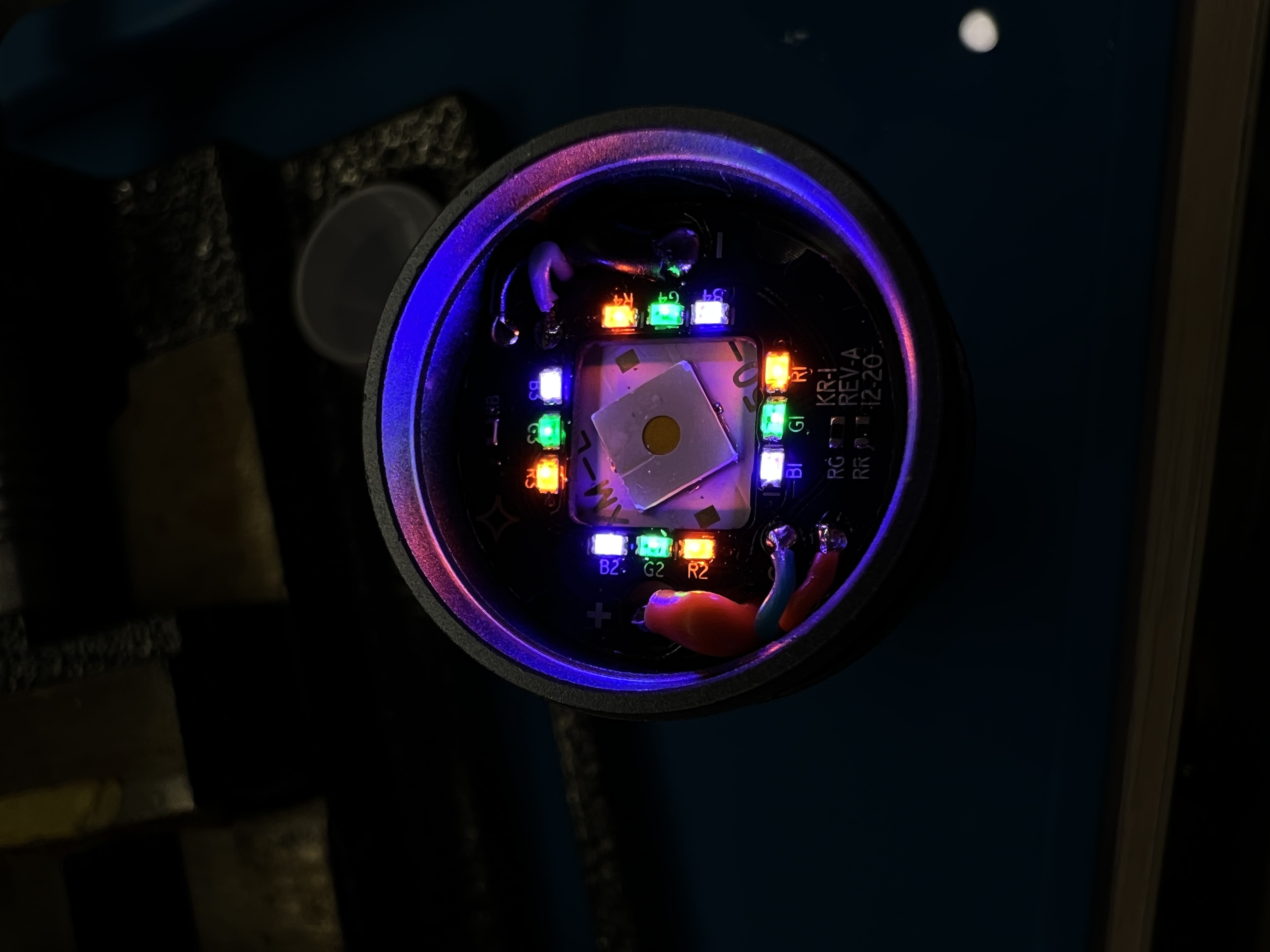
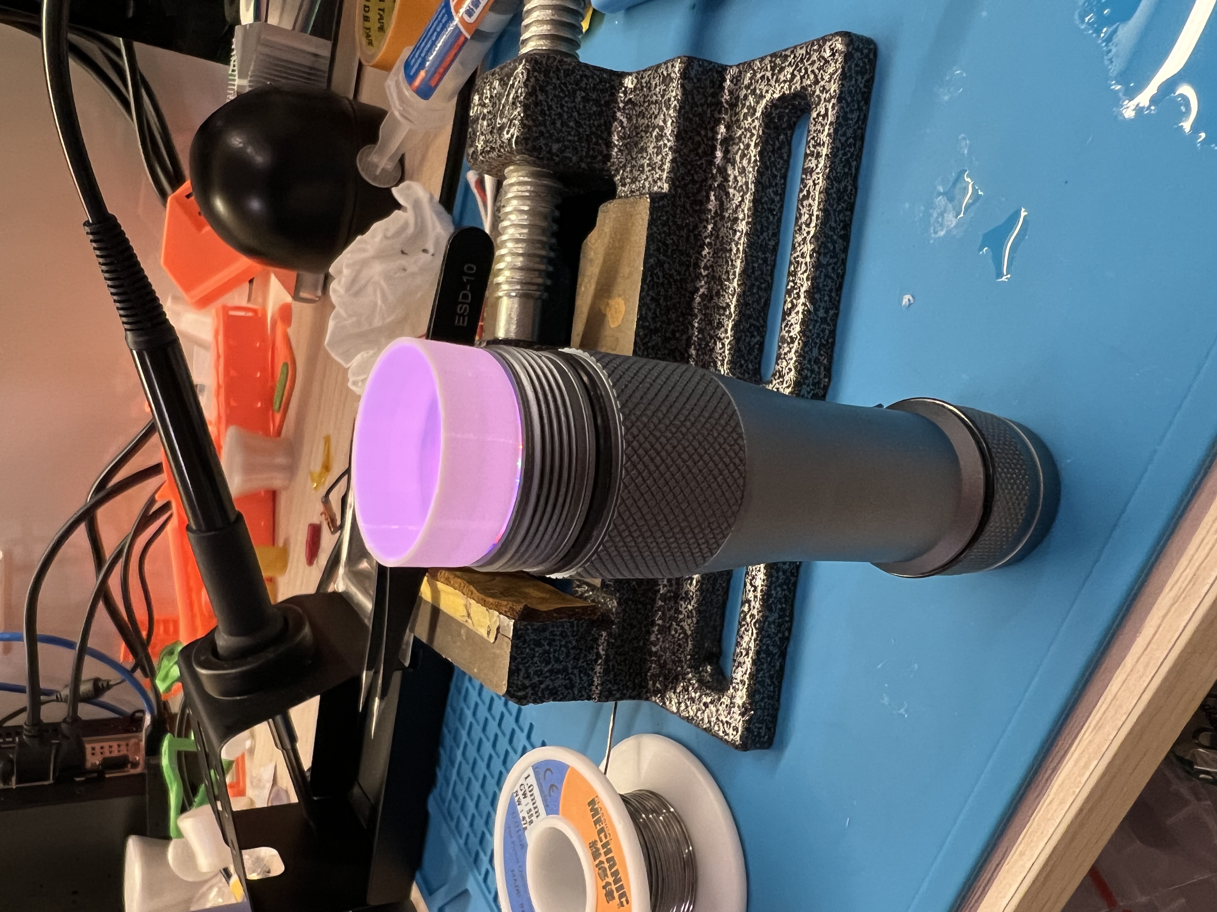
High mode: left - no resistor added, right - 510Ω resistor added

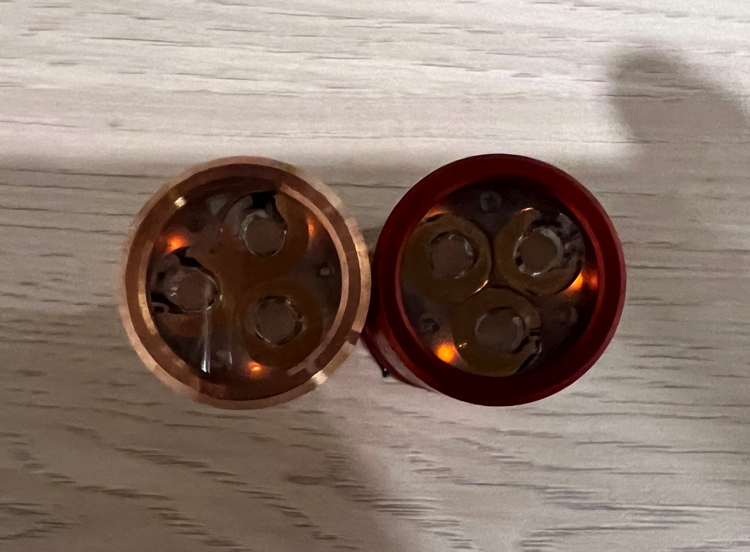
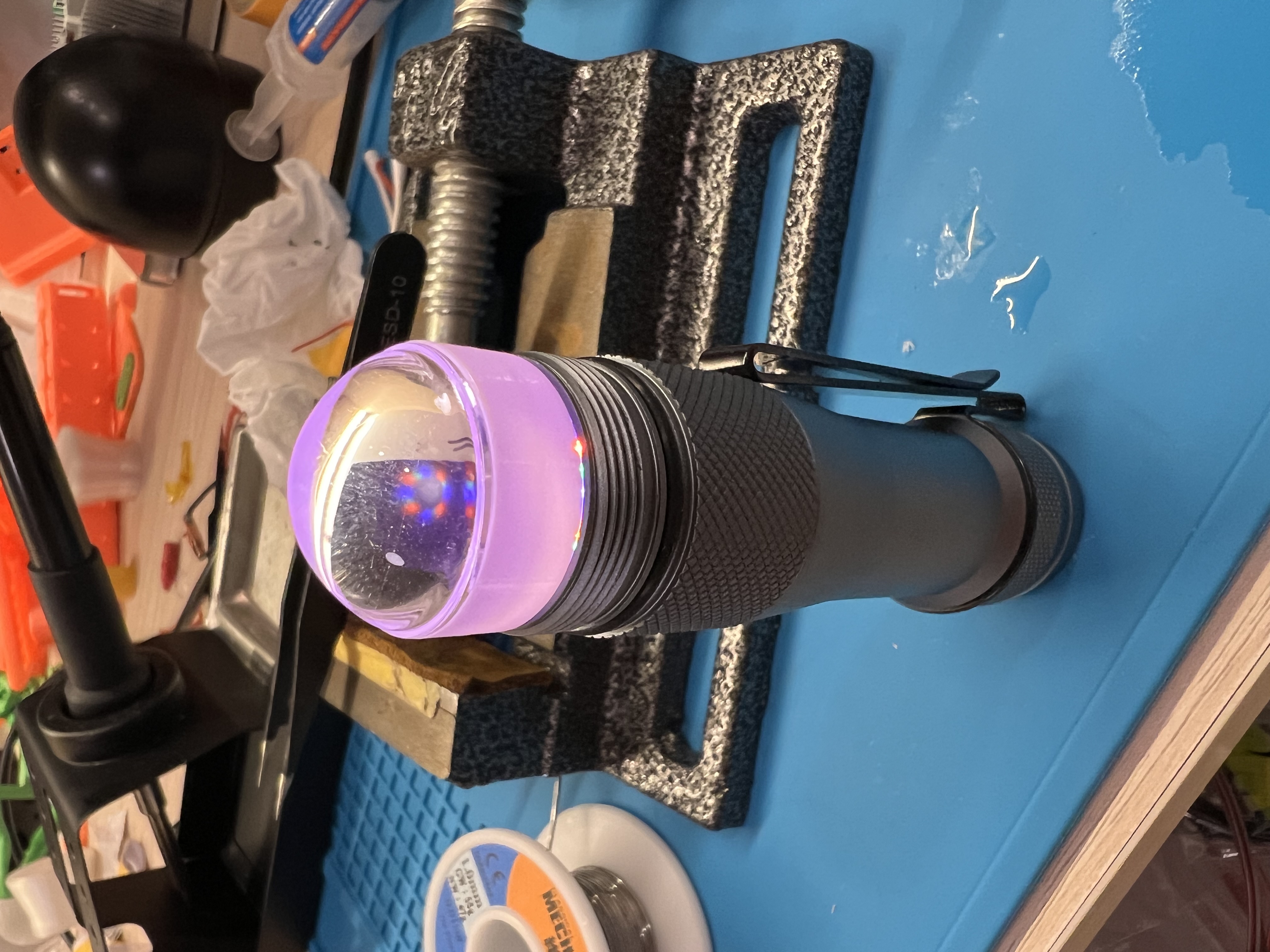
Low mode: left - no resistor added, right - 510Ω resistor added

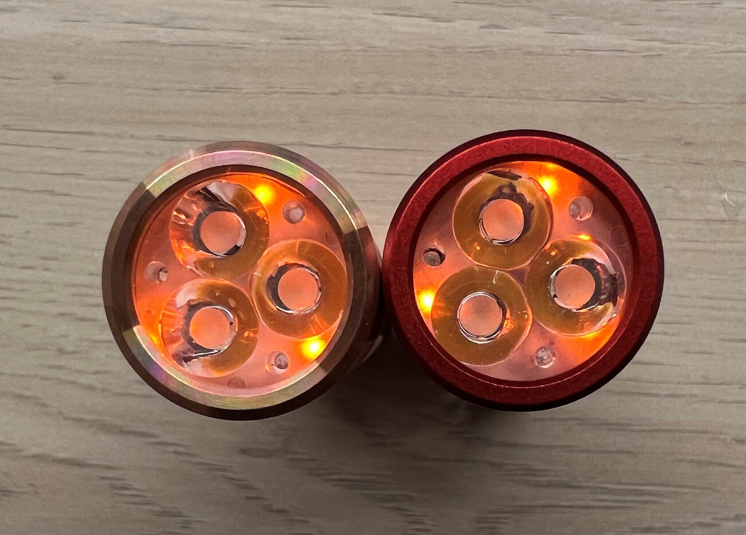
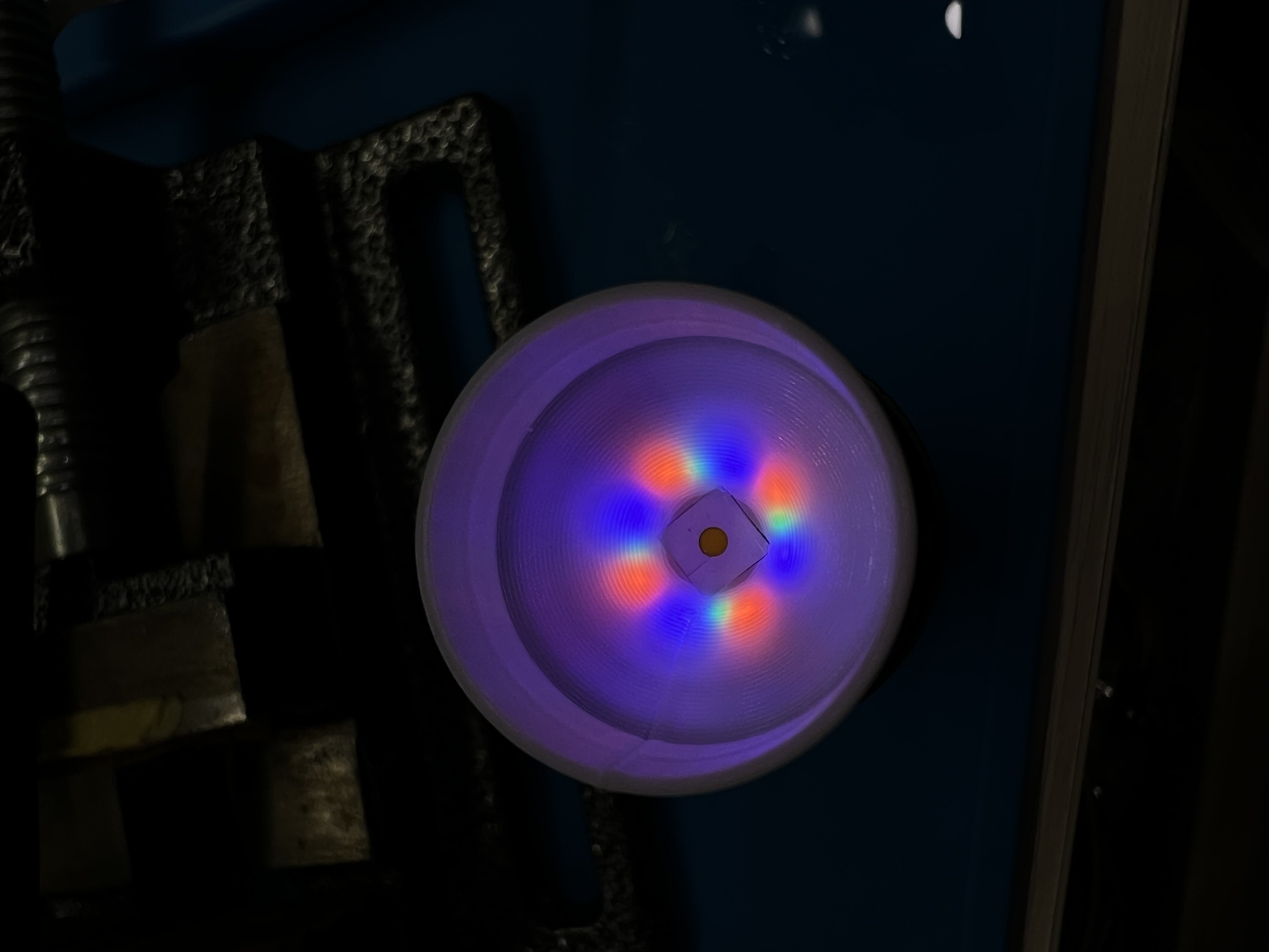
High mode after modding: 510Ω resistors added to both lights, much better

5
submitted 1 year ago* (last edited 1 year ago) by [email protected] to c/[email protected]
 

I printed a new spacer for my FW1Aspheric to project the internals onto the wall lol.

Video

[–] [email protected] 2 points 1 year ago

Thank you. I hope so too, and high CRI!

I just saw this posted over at BLF (credits go to koef3 and Simon from Convoy).

The tint of that sample is at or above BBL. Fingers crossed for some rosy ones when they are actually released. Though I would not use an apheric lens to make a square beam out of one. And the reflector options for 5050 LEDS in the FW1A mean that it won't be as throwy as a CULPM1 in a smooth reflector.

11
FW1Aspheric (lemmy.world)
submitted 1 year ago* (last edited 1 year ago) by [email protected] to c/[email protected]
 

It took me a while but I finally completed this mod, which started out as a FW1A Pro. This is what I did:

  • FET+7+1 driver upgraded to T1616 with aux support
  • Orange, green and purple aux
  • Yinding 5050 3000k emitter (warm and rosy, CRI > 70)
  • 3D printed spacer (white PETG)
  • Aspheric lens

I am getting around 76000cd at turn on, which is very similar to what the Bean Master got with a CULPM1 and a smooth reflector. But remember this Yinding is 3000k and rosy with a duv of -0.0075, and I think this makes it very impressive.

The main reason why I used an aspheric lens is because I needed aux, and suitable TIRs are just not throwy enough. I would also like to try to put those tiny RGB aux leds between the emitter and a reflector in the future. Enjoy the photos (sorry that most of them are in the wrong orientation, I uploaded them with my phone and I don't think they let me set the orientation)

The driver

All wired up

Orange, green, purple aux

Moonlight

With spacer

With aspheric

FW1-Aspheric vs KR1 SFT40 from 5 meters away

Looking into the lens

[–] [email protected] 1 points 1 year ago

That’s the correct order

Stupid me, you are right. I can't tell "R" from "B" from the label on the actual board. I think I swapped all of mine on purpose because I wanted the sequence of colour change to go from outside to inside. Again, not that it matters, because none of mine are RGB lol.

[–] [email protected] 0 points 1 year ago* (last edited 1 year ago) (2 children)

Perfect soldering as expected. I can't help it but my OCD has made me notice that you have the red and blue wires swapped on the aux board, not that it matters in this light.

Also is that moonlight level? The lowest few levels acted weird before you disabled dynamic underclocking. I have been doing some experiments myself, with dynamic unclocking enabled and disabled. I ended up making a new smoother ramp while keeping it enabled.

Btw, what happened to your anduril2 fork? It is no longer visible on GitHub, did you make it private?

[–] [email protected] 1 points 1 year ago (2 children)

I love them, but with the availability of the T1616 adapter, I feel like I need to push them all to the limit and have 3 colours for each light, even if the colours are the same lol.

Here is a video of it in action. And another.

[–] [email protected] 0 points 1 year ago (4 children)

Yea I don't own one yet, but it should be around 5.6mm to 5.7mm.

I can try making a version with the LEDs closer to the 3535 cutout

That would be great if you could, thanks.

[–] [email protected] 1 points 1 year ago (1 children)

I am looking into sourcing some of these RGB leds to try, and discovered that there is an even smaller model available.

B36S3RGB is 0.69 x 0.69mm. These are the ones you are using.

While

B36L3RGB is 0.65 x 0.65mm. Have you thought about using these?

I have not studied the datasheets in detail but from a quick glance, apart from the size, they seem to be identical otherwise.

[–] [email protected] 1 points 1 year ago (6 children)

Awesome! Do you think if I can fit these RGB leds under an original FW1A reflector with the smaller opening (not the crappy FW1A Pro reflector)? If I can eventually find one that is.


Hey all is my first post here and it looks like the main photo and a couple other photos below are not in the correct orientation.

I just got some new parts in to build a couple of throwy FW1A with aux (still waiting for the aux boards from OshPark). I got several different aspheric lenses, TIR optics that have been recommended in the past and the round-die Yinding 5050 emitter in 3000k (See the Opple 3 data below).

Still got some work to do as I need to work out which aspheric to use and the correct focal length which gives the most throw. After that I need to design a 3D printed spacer for the aspheric to sit on.

Edit: I like this emitter already, throwy (small emitting surface), warm (3000k), rosy (duv -0.0025!), and CRI not that bad! It is supposed to take up to around 8A of current I think.

view more: next ›