Hello!
I've been scratching a design for my new keyboard and wanted to try something fun. It's gonna be a 34-key unibody split, but I thought it would be cool to use the space in the middle for something fun. Many parts like cirque touchpads, roller encoders and such are hard to obtain in my area, so I didn't bother. Then I found a post by LazaroFilm with a small smartwatch LCD made by WaveShare and thought it would be a fun idea. I browsed their catalogue and noticed that none of the models are ideal for the job. The RP2040 touch LCD lacks GPIO and mounting points, the RP2040 LCD is pretty cool, but not having touch support is a bummer. Finally I thought that maybe it's better to go with a separate controller like a pico, and an 1.28" Round Touch LCD. It has touch support (duh) and 4 mounting screw posts. Pretty good. My only issue is the 13 pin JST connector used to hook it up to an MCU. It's gonna be a PCB design, no hand wiring, so I don't want a mess of cables dangling around. If only I was able to hook up a goldpin connector, or something, it would come together pretty clean. I was toying around with an idea of designing an adapter board, but there's not much room to play with and the pins are pretty tightly spaced (1.25mm). Also, it would be really great to come up with something that can be easily done without special equipment. All I have is a soldering station. No hot air, no nothing. I'd love to be able to design something that anyone can make at their desk.
I'd be grateful for any clever ideas. Thanks in advance! Cheers!
Hey! Glad my project inspired you! If you want more pins on the WS touch module, you can use an i2c expander board. It uses only two wires for SDA and SCL (plus two for power) and gives you a bunch of digital pins. And there is one i2c port available on the board (I’m using it to connect an IMU in my other project.
For mounting the board I clamped it between a ring and some tabs holding the module down (I’ll link to photos soon) I also looked into QMK integration and it seems it would be doable, but would require some extra coding to make the touch interface talk to QMK. Then you would still need custom firmware to animate the screen.
Also for the screen, I recommend looking into LVGL. It’s a library that allows you to build reactive interfaces easily. It even had a UI builder app where you can drag and drop your elements to make your interface. It’s. Bit buggy but the best I found.
Lastly, my idea for my trackpad project right now is to actually use it separately from the keyboard entirely and have a usb splitter hidden in the case to connect both.
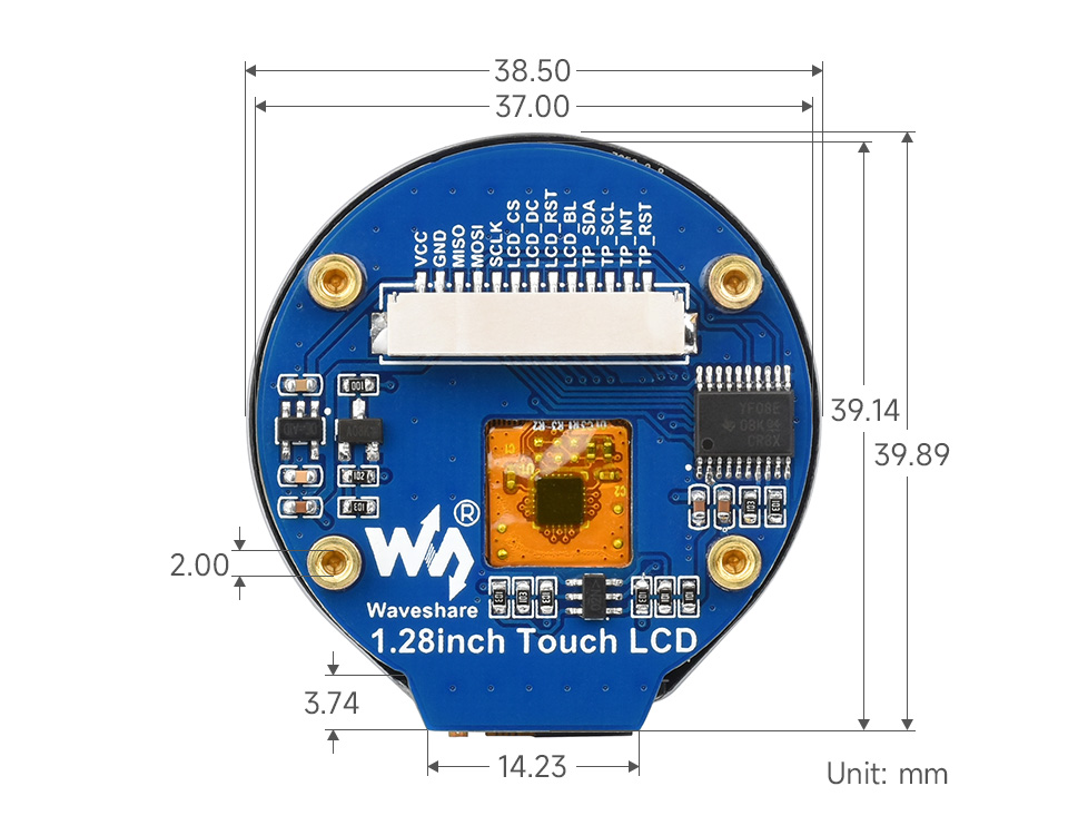
It's not exactly the same module, but similar. Pretty much the same thing but without the RP2040 MCU on board. I picked it up mainly because of the M2 screw posts. Too bad it doesn't use regular goldpin headers like the one without touch... It would make things so much simpler. I'd really like to avoid having a mess of tangled wires, but it would require me to find a connector that plugs directly downwards. Just like goldpin does, only twice as tight.
FYI, the non-touch version doesn’t use standard pin sizes. They’re much smaller (I got one and was super disappointed). For the connector. Right now I have a tangle of wires but I’m planning on cutting them and solder them. The benefit of the connector is that it makes it super easy to remove the module. To keep wires clean, you can braid them, or keep them together with some heat shrink.
Ugh. That kinda sucks. Although now that I actually took a look, it's written in the specs. It's 1.27mm goldpin. Less popular, but still pretty simple to get around. I think I might actually be able to convert my module from JST to 1.27mm goldpin with something like this. The difference between 1.25mm and 1.27mm across 13 pins should not be big enough to make a difference. I hope...